It is possible to link an attribute to any other attribute with:
A mathematical expression;
A curve describing the value of the attribute in fucntion of the value of another.
In order to add/edit/delete a link, the user must click on the link icon after the attribute
value in the parameter area:  . This attribute will be the driven attriute.
When an attribute is linked, its key icon is changed to:  .
.
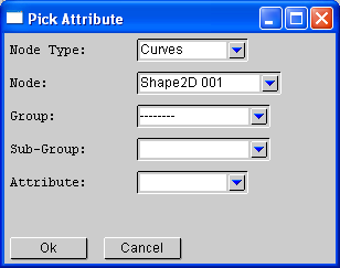
In order to select a driver attribute, Albatross3D is providing a 'Pick Attribute' window.
Picking an Attribute

Selecting an attribute can be done from top to bottom.
First, select the object node type. The node combo-box is automatically filled in.
Select an object. The group combo-box is filled in with the available groups.
Select a group. The sub-group and the attribute combo-boxes are filled in.
Press the 'Ok' button to select the attribute designated in the attribute combo-box.
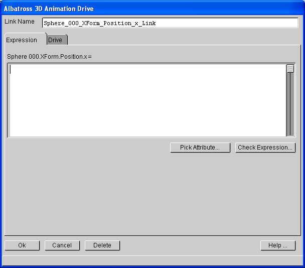
Expression Link

An expression link defined the values of a parameter by a mathematical function.
The available variables are:
t: the current time, in seconds;
f: the current frame number;
any avaiabale attribute, where spaces in the name are replaced by an '_' (underscore).
The two defined constant are: pi, e.
The defined functions are:
the operators: '+', '-', '*', '/',
'^' (rasing to a power), '%' (modulus), '|' (logical or), '&' (logical and),
'==' (equality test, return 1 if equal, 0 otherwise), '!' (logical not),
'!=' (inequality test), '<', '<=', '>', '>=';
sqrt: square root;
sin: sinus;
cos: cosinus;
tan: tangent;
asin: arc sinus;
acos: arc cosinus;
atan: arc tangent;
log: base 10 logarithm;
ln: natural logarithm;
ceil: round to the nearest integer lower or equal;
floor: round to the nearest integer greater or equal;
round: round to the nearest integer
abs: absolute value;
rand: returns a random value between 0 and 1.
All angles are expressed in degree.
The 'Check Expression...' button allows to verify the validity of the expression.
Function Link

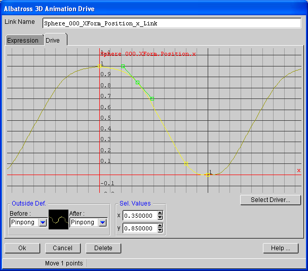
A function link defines the values of the driven attribute by a curve dependant of the
value of a driver attribute.
The outside configuration is indentical to the one of the curve editor/dopesheet.
The outside curve (before and after the first and last point) is displayed in dark yellow.
The bright yellow curve is the one that can be edited.
Click on the point to select it, 'Shift' Click on a point to add it to the selected points.
When a point is selected, the tangent handles are displayed.
Right Click on the curve to add a point.
Right click away from curve opens the following popup menu:

The following command are available to change the curve view:
zoom: mouse wheel or 'Ctrl' and 'Alt' left drag;
pane: 'Alt' + left drag;
'+', '-': zoom in, zoom out;
'w': center;
'del' key: delete the selected points;
A driver must be selected to activate the link, with the 'Select Driver...' button.
The input boxes allow to change the point coordinates with numerical values.
 . This attribute will be the driven attriute.
 .
.


